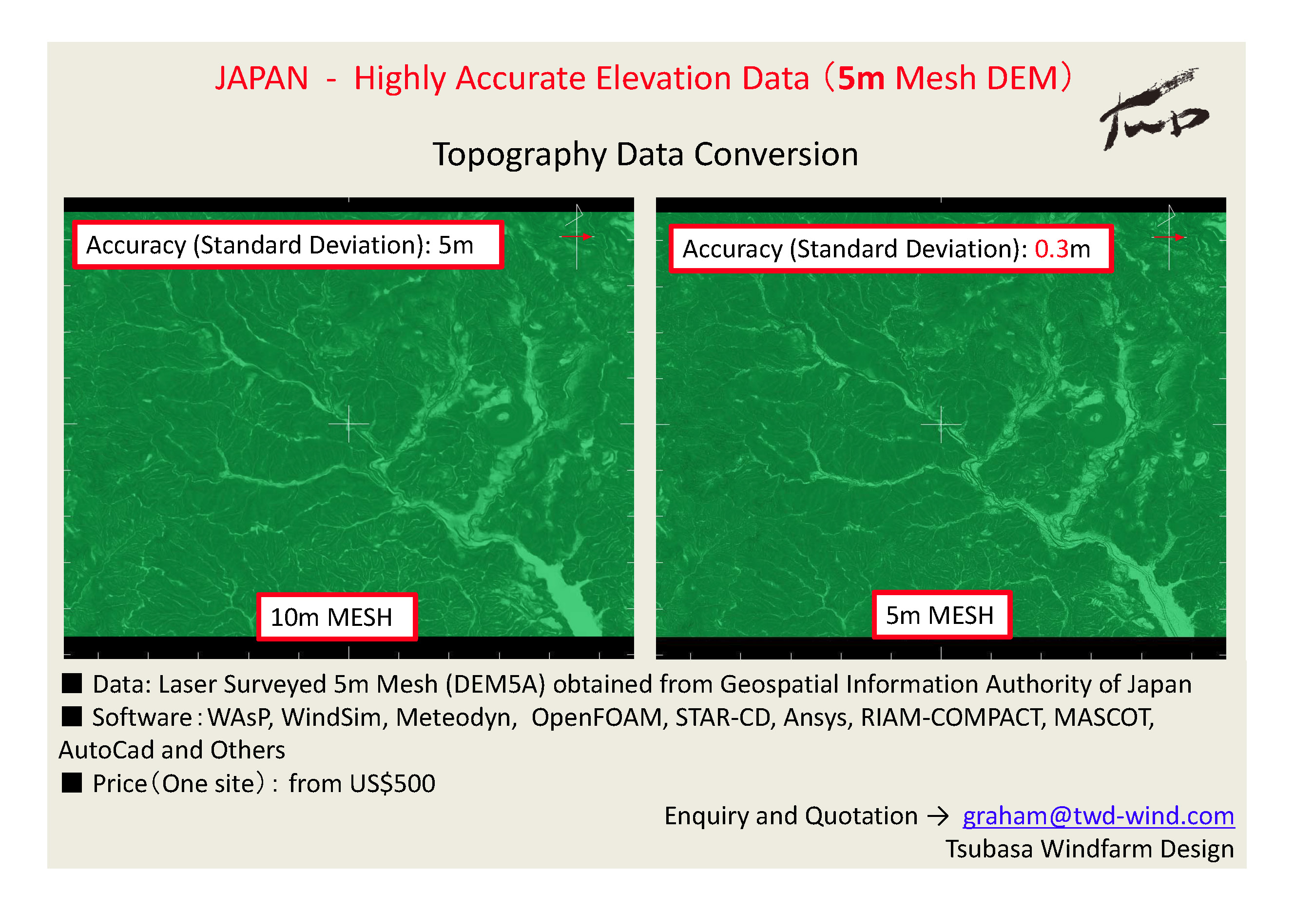
In order to get accurate CFD results, It is essential to use accurate topography data. TWD converts highly accurate 5m mesh data obtained from the Japanese government and convert to a format you want. Click here for more details !
Wind Energy Restoration
I first came to Japan in 2003. In the past nine years, wind energy has not really progressed much. Nuclear-oriented electrical utility companies were passive about it, government was not enthusiastic, and the public was pretty much unconcerned where they get their electricity from.
The day March 11, 2011 has changed everything.
The public now shows a very high level of interest, and the government for the first time displays the necessary willpower to push for more renewables. However, there are lots of problems facing the wind industry, namely turbulence, lightning, difficult transportation, noise, bird strike, visual impact, and so on. Because of all these problems, there are people or academics who believe we should forget about onshore wind and move on to offshore wind. But I do not agree with that. Solutions exists for these problems if we are persistent and creative enough. Among all renewables, onshore wind is cost-effective enough to play a major role and make a significant contribution.
There are some people who totally dismiss wind power and think it is useless, such as Tokyo Governor Shintaro Ishihara, Akihiro Sawa of the International Environment and Economy Institute, and Tokyo University Emeritus Professor Itaru Yasui. What these guys have said really burns me up and further motivates me.
Fukushima was not just another nuclear accident: it has a very deep meaning in it. That is, the shift from unsustainable nuclear towards renewable energy is the only way forward. Increasing numbers of Japanese are believing the same. To fulfil this expectation, I will give it everything I have and strive to do my best, until I climb and reach the summit.
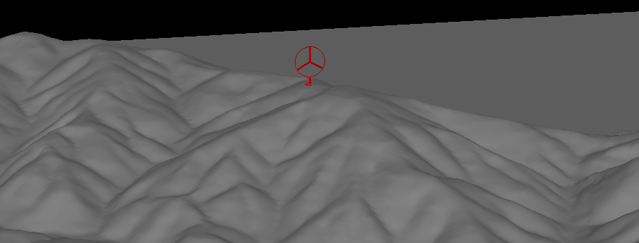
Chapter 7 - LES CFD for Mast Position - AGR Renewables
Everyone knows excessive turbulence can be bad for wind turbine but some people forget it can also be bad for mast.
Needless to say, the use of these measured mast data can lead to wrong turbine selection and high error on production estimate.
This particular site presented to me is located at Scottish mountains, the topography of the site is moderately complex and I was given a preliminary layout.
As shown by the animation below, the LES CFD simulation predicted turbulent wind conditions at a number of turbine positions.
There are plenty of operating Vestas V80 in Japan and unfortunately from my own experience,
I know that terrain-induced turbulence does a a fair amount of structural damages on some of these V80,
in particularly the yaw components.
As shown by the animations below, the LES codes of RIAM-COMAPCT
predicts highly fluctuating wind speed and wind direction exceeding the IEC extreme wind conditions.
And obviously these extreme wind conditions translate into loads which goes well over the design load of the yaw components.
For quantitative details, click here for the technical paper,
which include a comparitive simulation using RANS CFD based software METEODYN.
Welcome any questions and comments.
Chapter 3 - Transient Killers
Right after giving my conference presentation at EWEA 2013, two REpower engineers came up to me and said
they totally agreed that the "transient" is important.
We all know loads and vibrations are caused by transient wind events.
Damagaes to structures, buildings and houses are mostly caused by gusty wind which happen in few seconds.
In the case of wind turbine, the temporal and spatial variations across the large rotor is the key in assessing
turbulence risk.
To illustrate what I am saying, I present here a real case, a wind turbine installed in Japan which has been suffering from a very high
frequency of yaw related failures and also blade damage.
The topography around the wind turbine is extremely complex with highly undulating terrain in close vicinity.
I carried out a CFD simulation and found both large vertical and horizontal wind shear is present across the rotor face.
As shown below, the large wind shear is a direct result of the terrain induced turbulence occurred in the upstream.
Time series obtained from the CFD simulation is compared with IEC Extreme Wind Shear (EWS) model and large deviation is found.
The large and highly fluctuating wind shear translated into loads which far exceeds the design limit.
It is therefore logical to deduce that the failures seen by the turbine is caused by the highly turbulent transient wind conditions.
Topography (60m hub with 80m rotor diameter)
CFD Results - Flow separation and Large vertical wind shear
CFD Results - Large horizontal wind shear
Chapter 2 - Turbines without heads and arms
On April the 7th this year, a low pressure system with the equivalent strength to a strong typhoon swept across Japan.
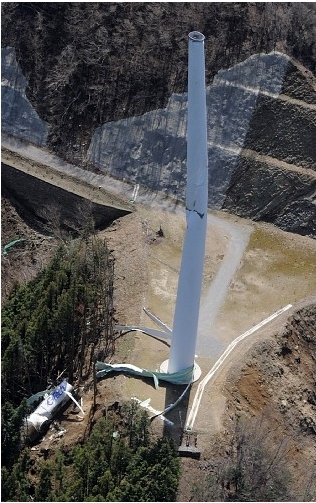
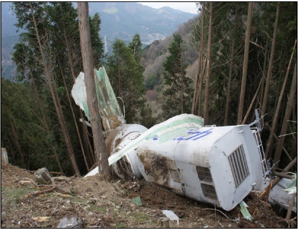
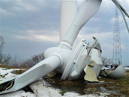
At around 5pm, one of the turbines at Kasatori windfarm suffered a catastropic event -
the nacelle and blades collapsed to the ground. Siginificant rotor overspeeding - maximum 57.78 rpm - was recorded in the
SCADA data. This is roughly three times the rated rotational speed.
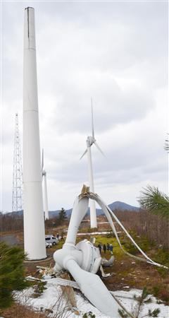
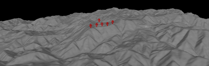
About a month earlier, a similar accident happened at Taikoyama windfarm.
Wind speed was only around 15m/s at the time of the accident. Inspection revealed cracks at the "neck"
section of the tower for five of the six turbines in the windfarm.
Investigations are still ongoing, but the high turbulence level experienced by these low hub height
Lagerwey turbines is likely to be a major cause. I did a CFD simulation before and found that the wind
direction changes rapidly with large shear across the rotor face,
see Concept - Step 2 - Case 1.
I believe this accident marks the end of these six turbines which have worked hard for the last 11 years.
Given its location in Kyoto Prefecture, Taikoyama windfarm was intentionally built in response
to the adoption of the Kyoto Protocol. Unfortunately, the site's turbulent wind conditions were not
properly assessed and therefore the risks were unknown to everyone at the time.
In my next few articles, I will concentrate on how to assess the
turbulence risk for these ultra-complex terrain sites.
Kasatori Windfarm Accident
Taikoyama Windfarm Accident
Chapter 1 - World's Most Complex Terrain Windfarms
I gave a presentation at EWEA 2013 earlier this year and in my speech
I mentioned the terrain in Japan can be classified as highly complex.
The topography in Japan is indeed very different and unique.
Recently someone from Germany said to me "Japan is the motherland of complex terrain".
His words motivated me to start this blog and to present here what I think are some of the most complex terrain windfarms in the world.
A total of 6 sites, 5 of them from Japan and one from New Zealand.
If you know of any ultra complex terrain windfarm that deserve a place here, do contact me.
Needless to say, complex terrain brings considerable challenges.
It is essential to characterise the flow correctly, quantify and predict any significant risk before we build the windfarm.
And finally, I am sad to tell you that recently two of the windfarms presented here suffered a catastrophic accident,
which I will write about in the next article.
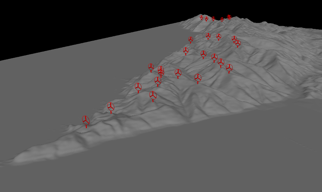
Shinizumo, Shimane Prefecture, Japan - Vestas V90 x 26 Google Earth File
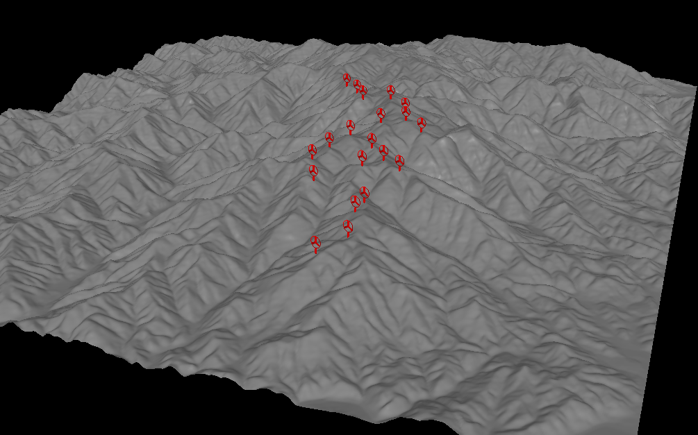
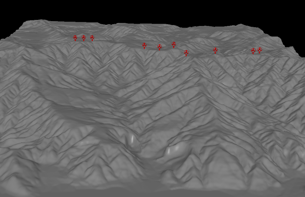
Shiratakiyama, Yamaguchi Prefecture, Japan - GE 2.5-88 x 20 Google Earth File
Taikoyama, Kyoto Prefecture, Japan - Lagerway 750kW x 6 Google Earth File
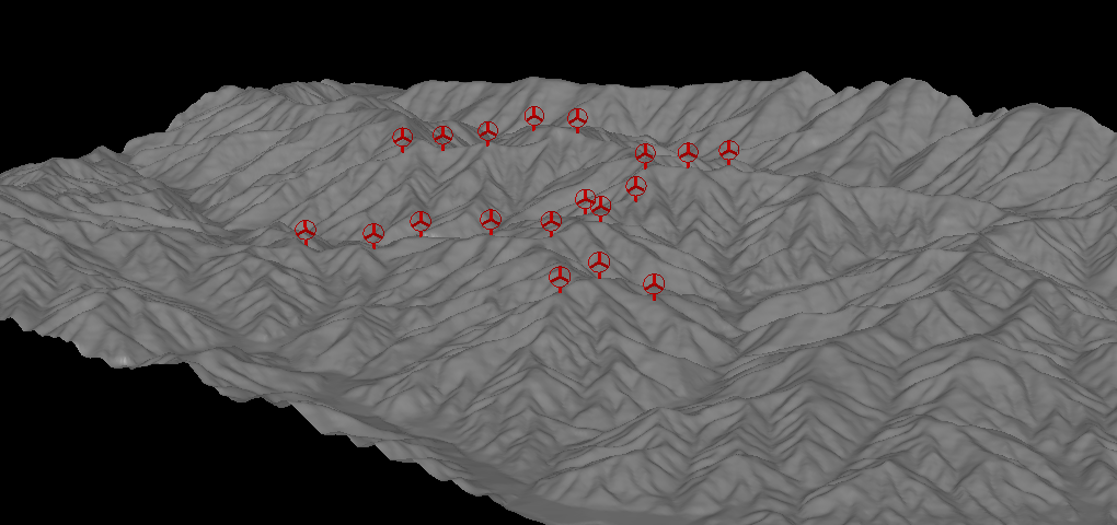
Kihoku, Kagoshima Prefecture, Japan - Siemens SWT1.3-62 x 16 Google Earth File
Kasatori, Mie Prefecture, Japan - JSW J82-2.0 x 19 Google Earth File
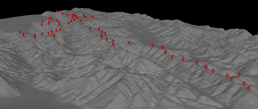
West Wind, Wellington, New Zealand - Siemens SWT2.3-82 VS x 62 Google Earth File